Point Cloud Studio
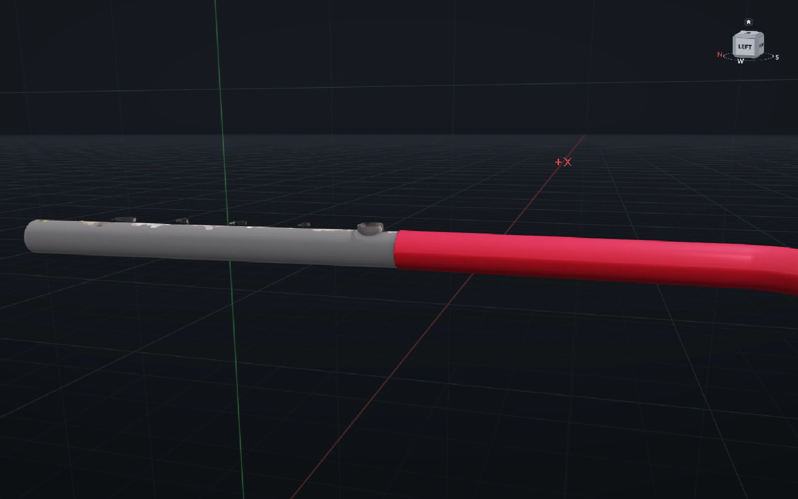
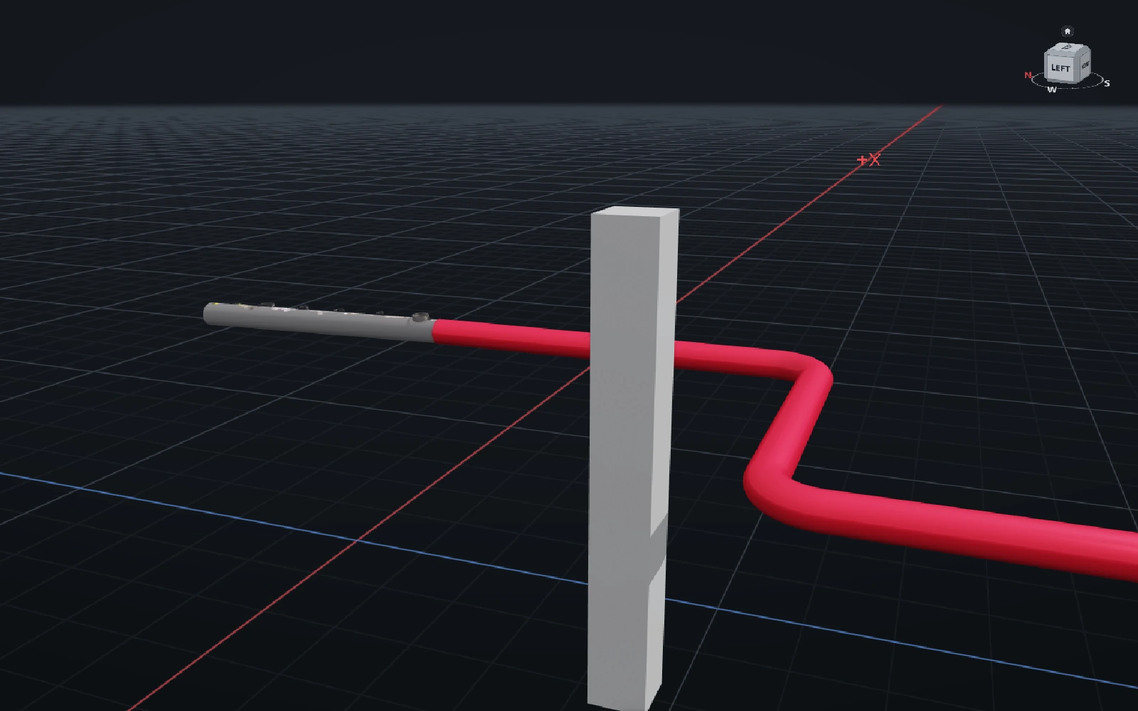
Turn the scanned pipe into the start of a new line.
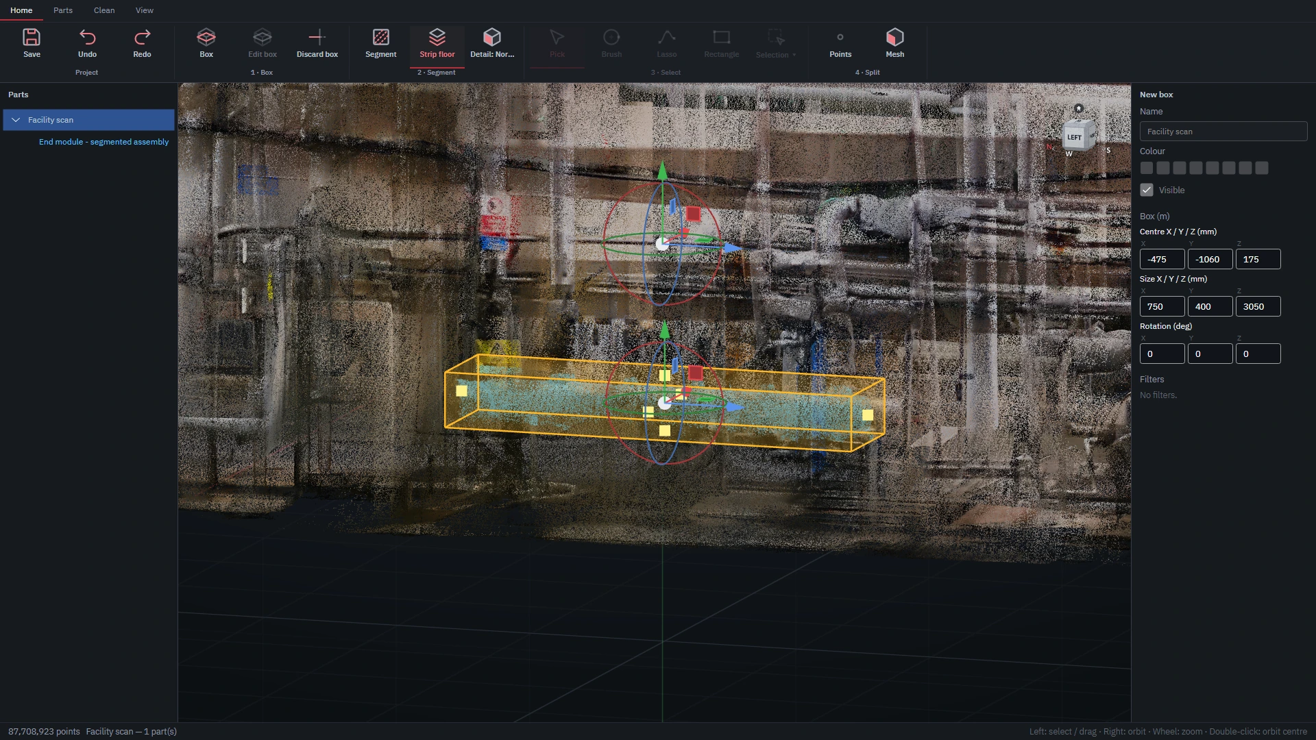
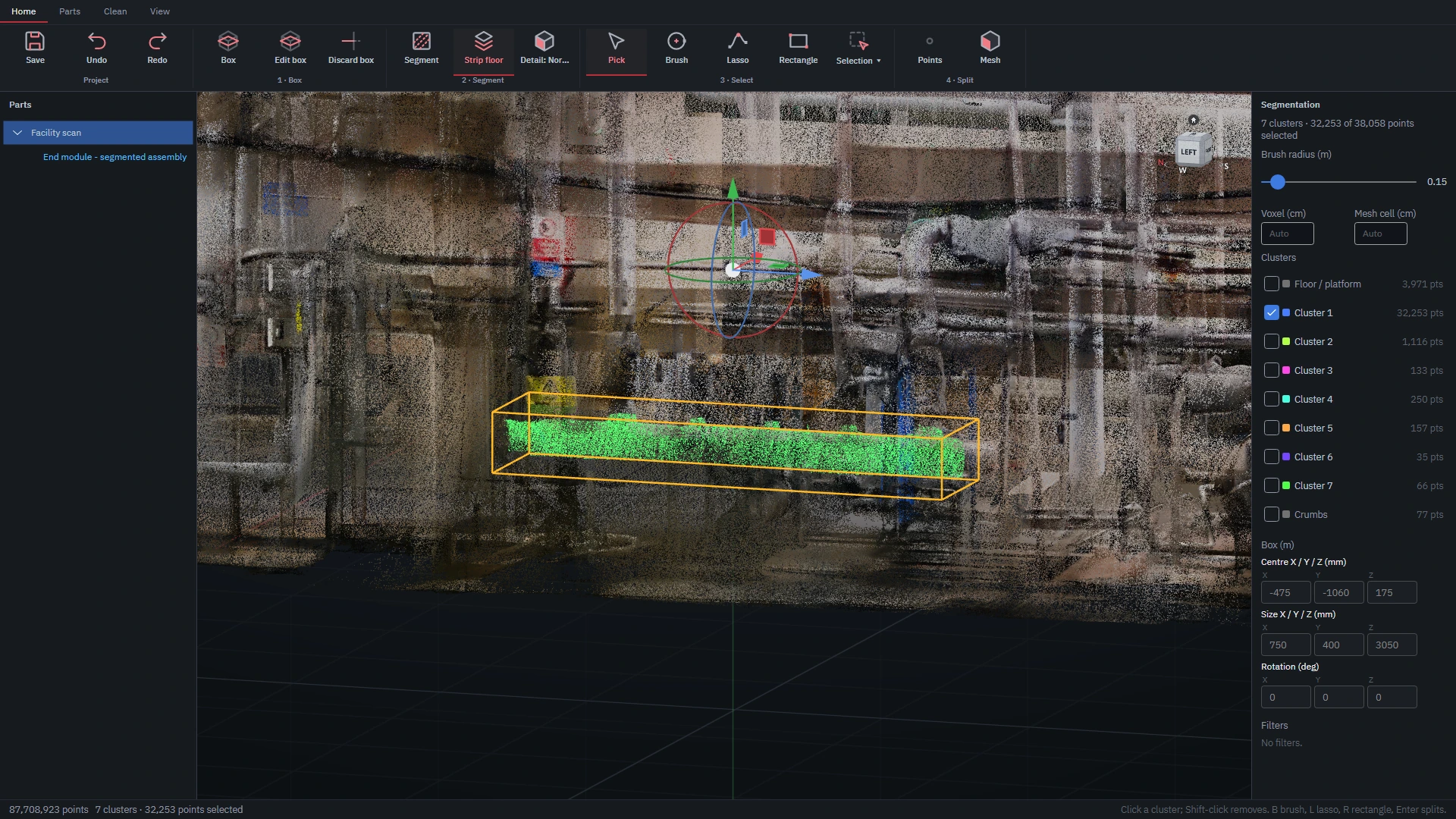
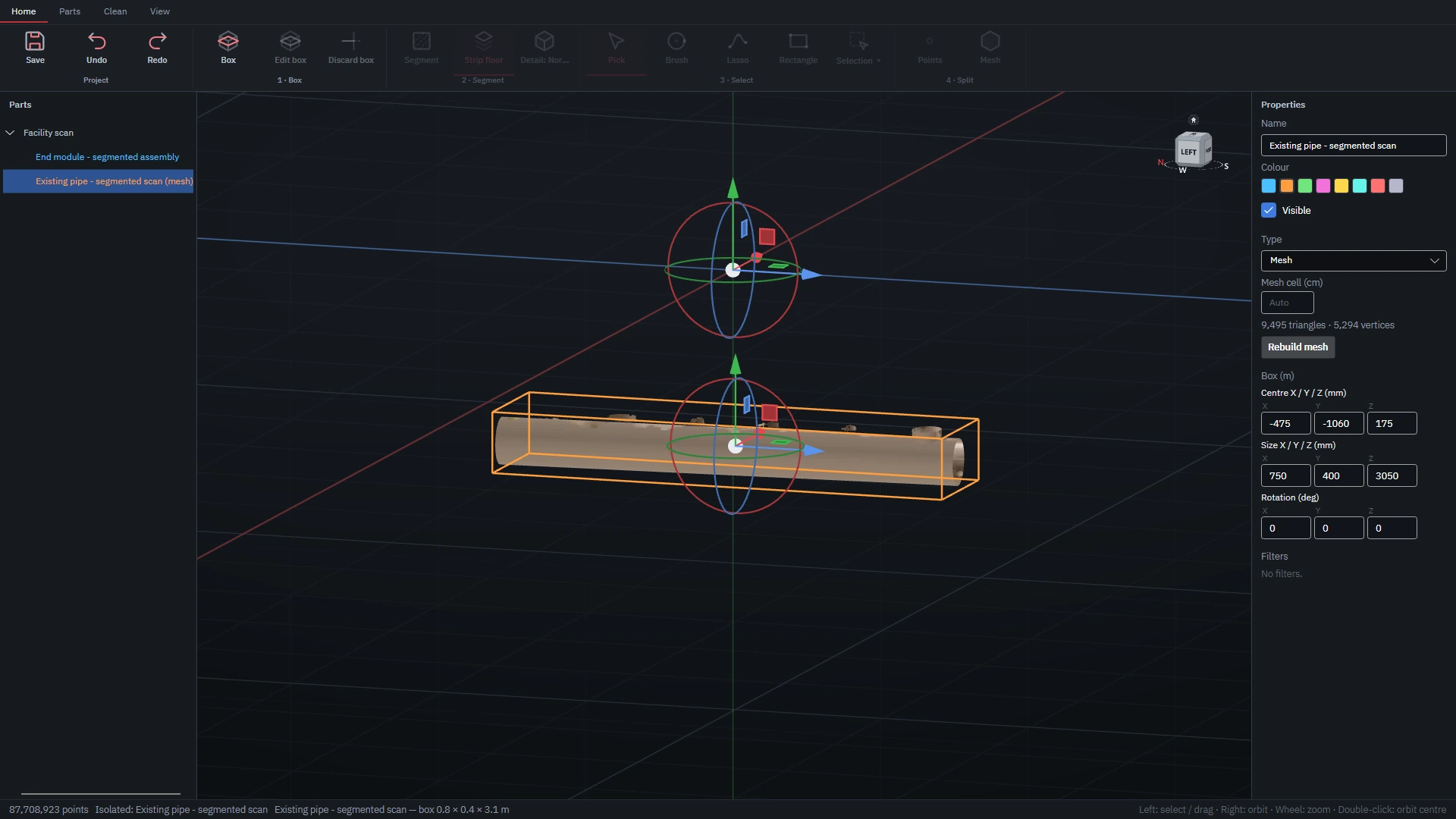
Separate the pipe from the scan, create its surface mesh and connect a new line to its end. Select a stage to follow the process from point cloud to piping model.

Process the scan, inspect equipment and design pipe routes. Resolve clashes in the model, then export isometric drawings and material lists.
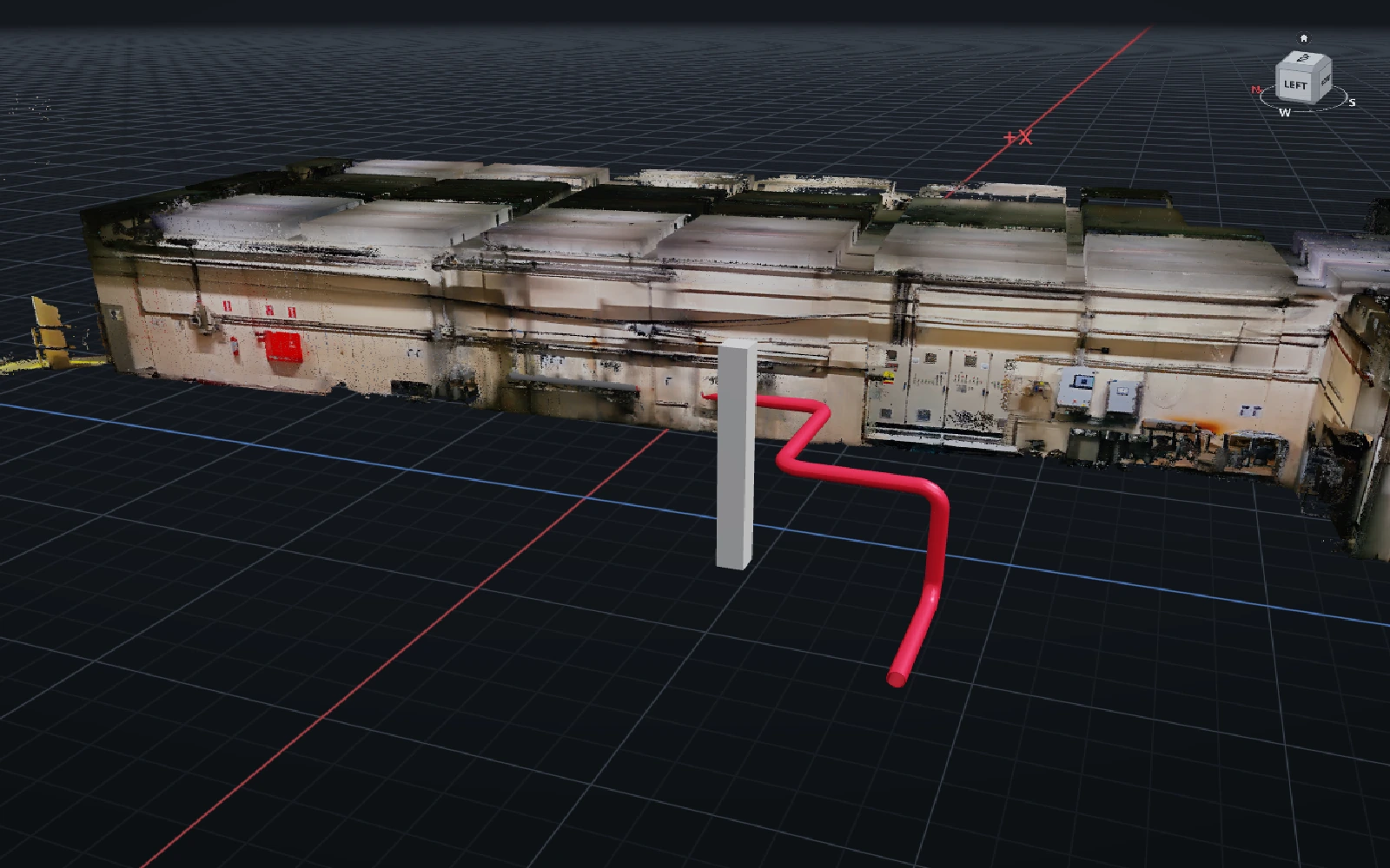
Prepare the existing facility, inspect equipment in detail, build connections and check interferences. Engineering brings these tools together around the same project.
Point Cloud Studio
Separate the pipe from the scan, create its surface mesh and connect a new line to its end. Select a stage to follow the process from point cloud to piping model.
Open Studio
Find the component you need in a large machine model through the feature tree. Review its identity, dimensions and position alongside the 3D view.
Piping
Build connected piping with equipment connection points, a line specification and catalogue parts. Check elevations, elbows, valves and supports in the facility model.
Clash Detection
Locate the two clashes at the column. Change the pipe route and run the check again. Compare the original and revised routes with their reports.
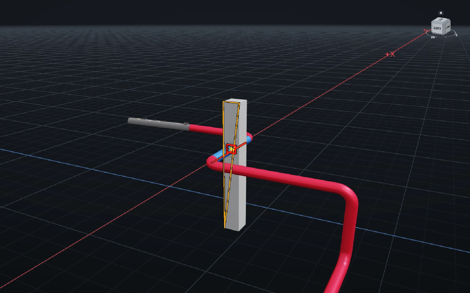
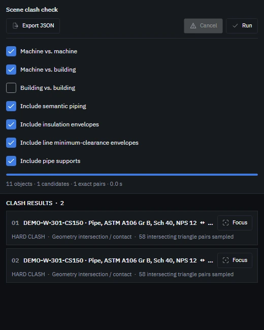
Two contact regions were found where the same pipe enters and exits the column. The relevant route section was shifted by 1.5 m while retaining its connection to the scan-derived mesh.
Download this check’s report ↓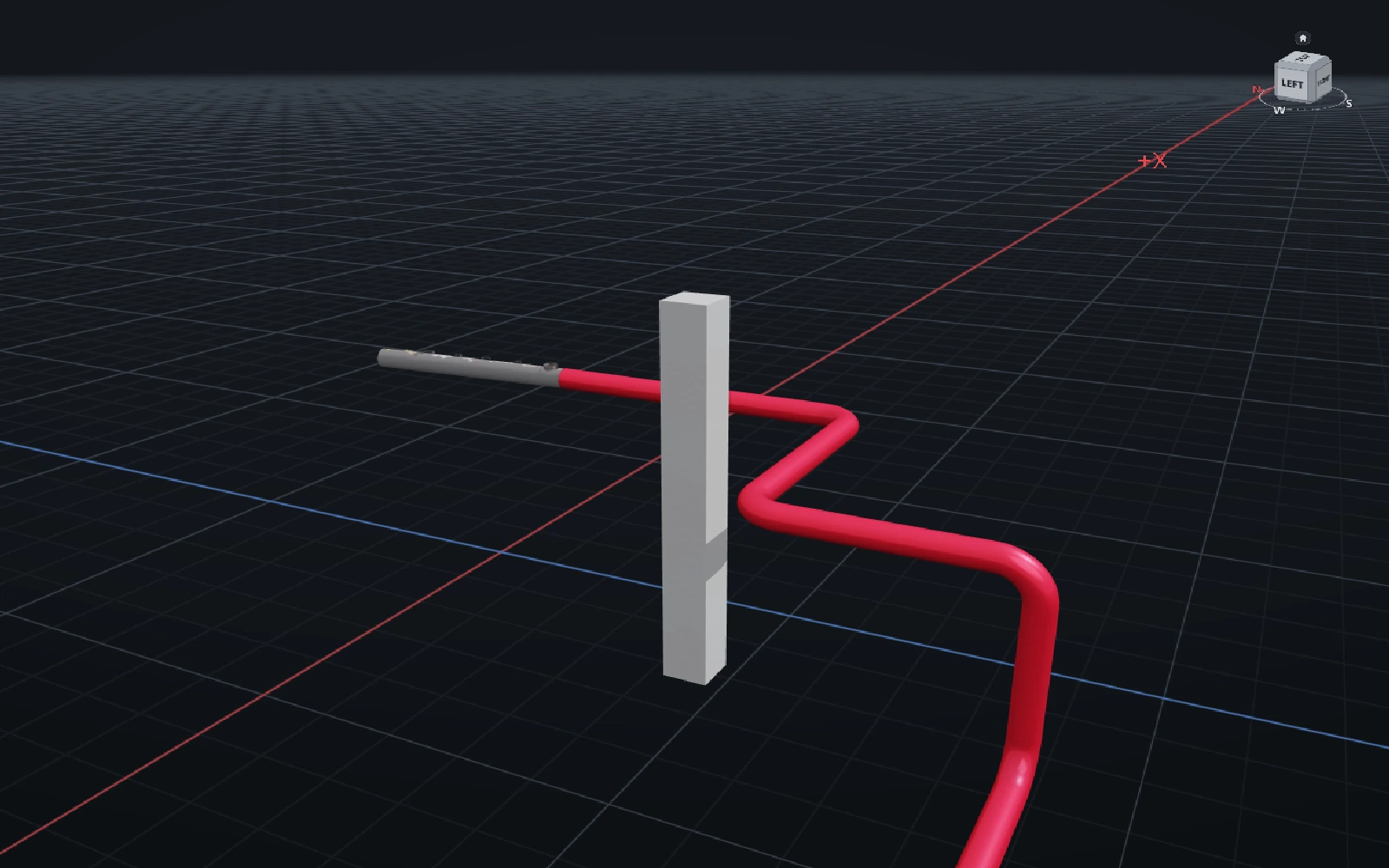
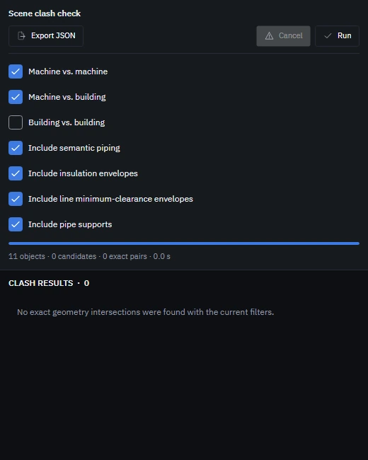
Two contact regions were found where the same pipe enters and exits the column. The relevant route section was shifted by 1.5 m while retaining its connection to the scan-derived mesh.
Download this check’s report ↓Checked: pipe mesh, column and new line. After adding the valve: 17 geometries, 0 clashes. Final report ↓
Watch the recording, from connection to correction →Extract a pipe from the scan and connect a new line to its end. Reroute around the column, add a valve and export the isometric drawing.
Riza, Elif and a dairy facility: Atlas proposes, the engineer reviews. The outputs shown belong to a demonstration project.
The video could not load. Check your connection and retry, or open the video directly.
Explore the five-page PDF of the new line connected to the extracted pipe mesh. The corrected route, valve, part and weld schedules come from the same demonstration project.
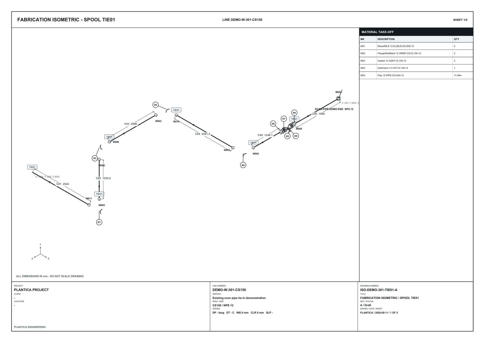 Enlarge the drawing ↗
 Enlarge the drawing ↗
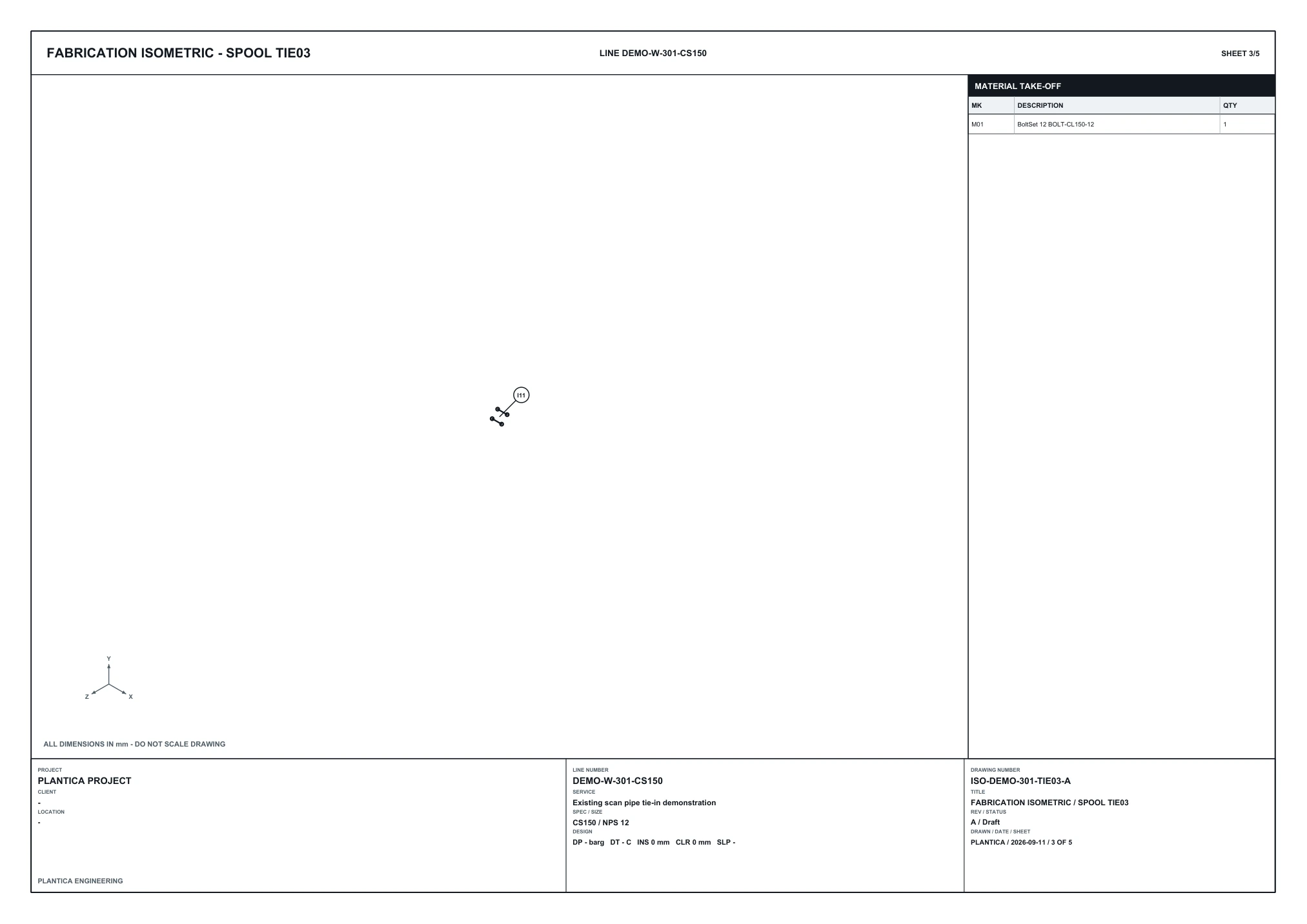 Enlarge the drawing ↗
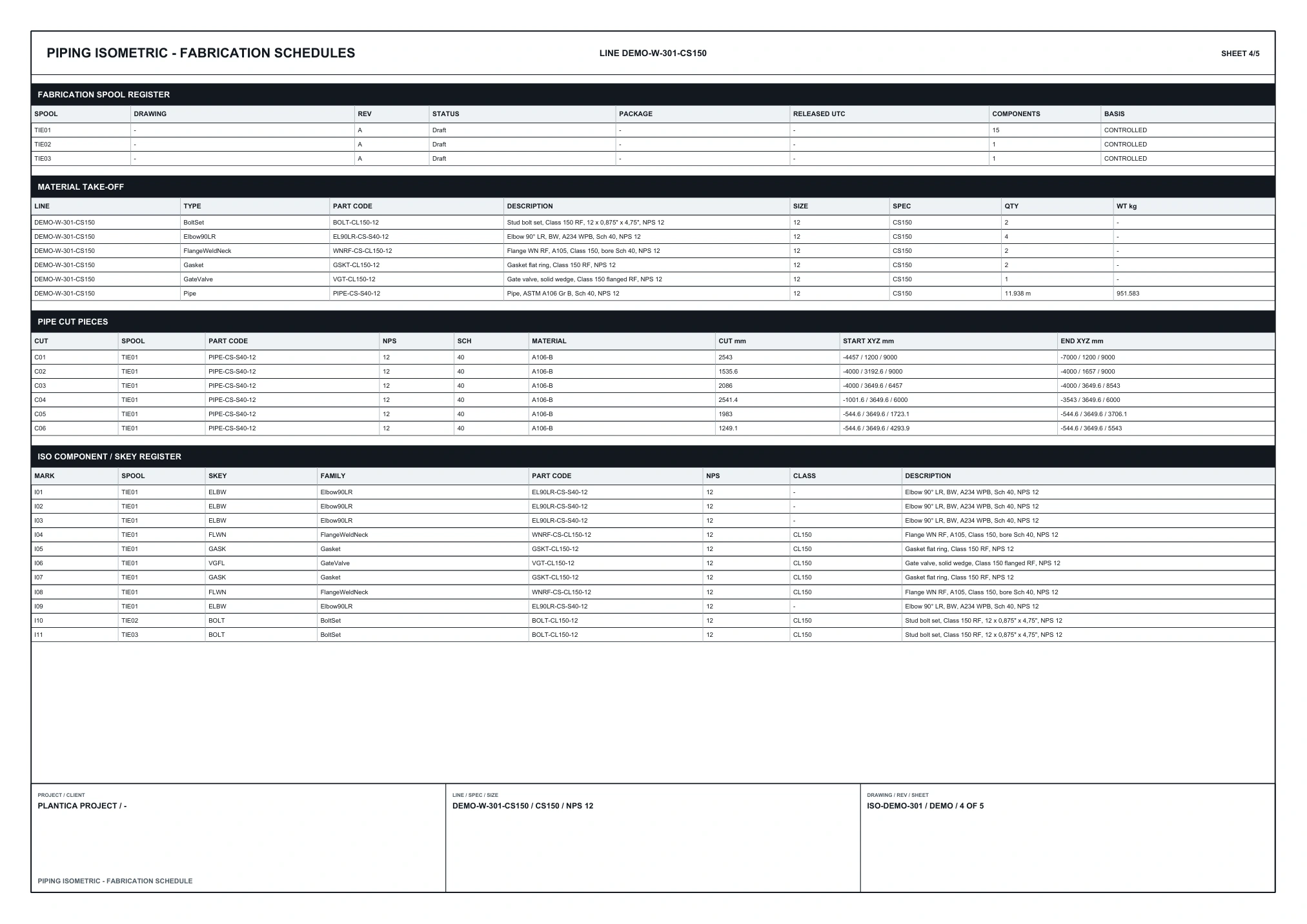 Enlarge the drawing ↗
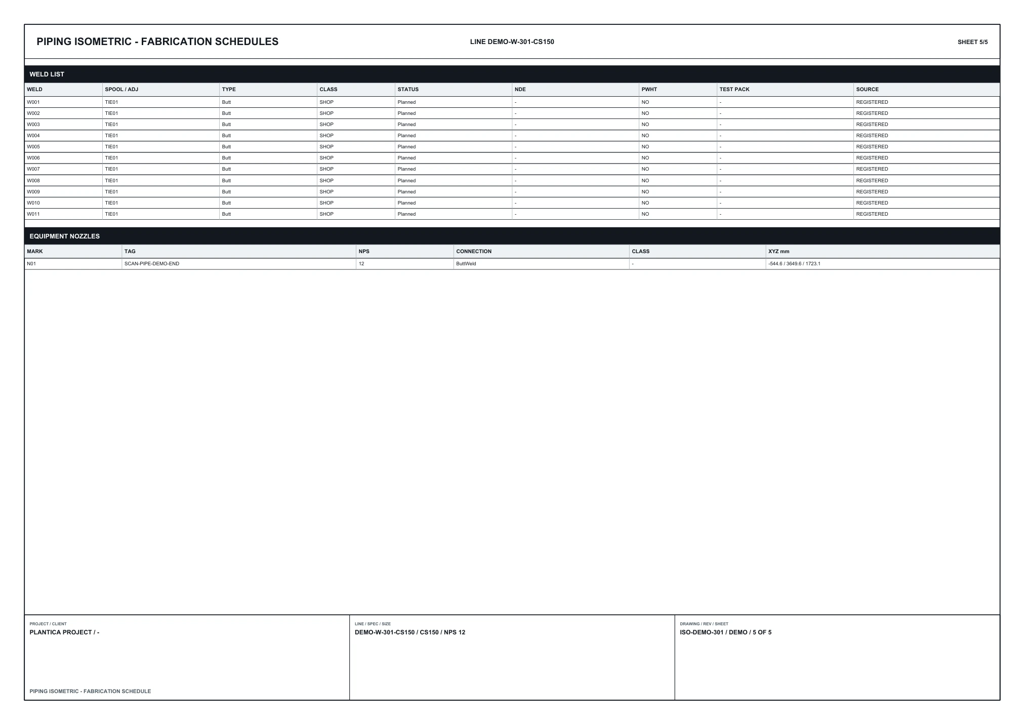 Enlarge the drawing ↗
The CS150 / DN300 line connects to the pipe extracted from the scan. Its other end is open for continuation.
A facility model or scan and the engineering question you need to resolve
Choose the facility model or point cloud you want to review.
Select the equipment, new pipe connection or clash area to inspect.
See the revision in the model. Share the drawing, clash report or material list with your team.
Customer contexts and example workflows for Plantica Engineering.
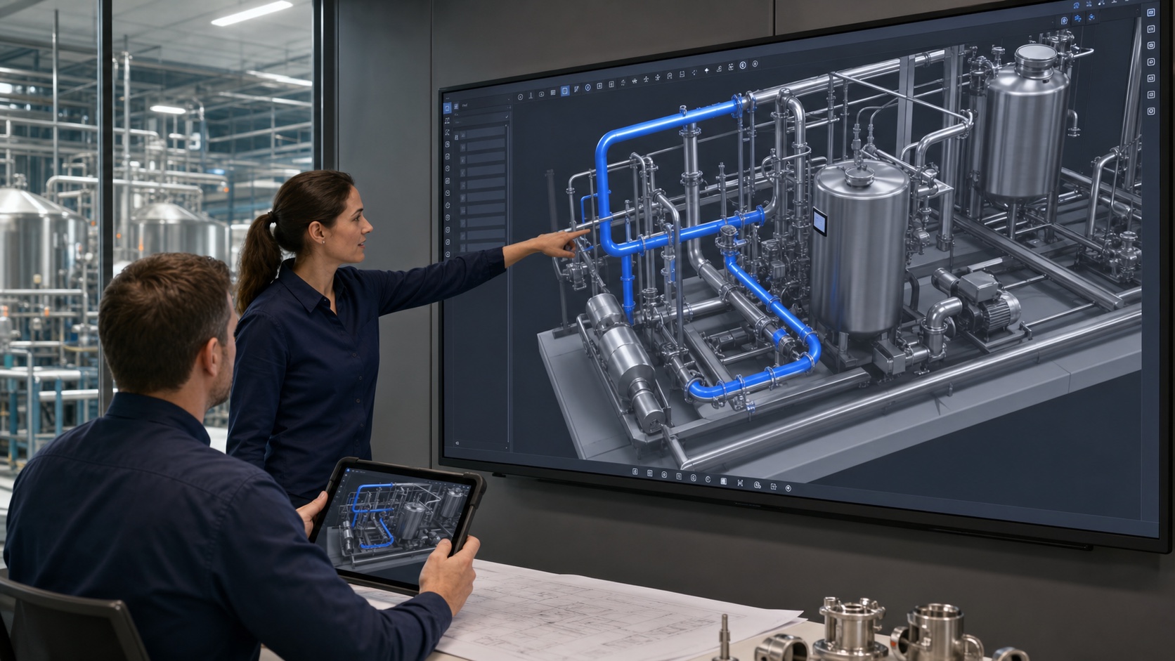
GEMAK · Liquid-food processes
A process engineering workflow reviewing tanks, pumps, valves and pipe routing together.
Explore the workflow →Example scenario · Facility retrofit
A retrofit workflow reviewing a new design alongside scans and existing facility geometry.
Explore the workflow →Plantica Engineering lets facility and process engineers review scans, CAD and new piping together. The published application recording extracts an existing pipe from a scan, connects a new line to its mesh and reroutes a clash with a column. The result can be reviewed with an isometric drawing and bill of materials. Watch the scan-to-piping recording
Clash checking compares the geometry represented in the model. A missing column or an outdated scan limits the review. Before installation, the project team needs to assess survey currency, coordinates, tolerances, installation access and maintenance access. Read the field-readiness engineering note
Crop the working region, apply noise and ground filters, and separate named parts. Generate a surface mesh from a part and export it to the library as points or mesh for reuse in the scene.
Machines, building elements, piping and steel can be included. The analysis uses actual part geometry and can assess pipe insulation and defined clearance envelopes. Results identify the objects involved and the contact region.
The demonstration uses the CS150 / DN300 catalogue: Sch 40 pipe, long-radius 90° elbows and a flanged valve. Catalogue entries reference ASME B36.10M, B16.9, B16.5 and B16.10.
Yes. The five-page PDF on this page was generated inside Plantica from the connected line shown in the recording. The isometric view, part schedules and weld schedules use data from the same model.
Bring your facility model or scan. Let’s work through the equipment review, clash check or piping question in your own project.